|
| Calendar |
| « April 2024 » | | Su | Mo | Tu | We | Th | Fr | Sa | | | 1 | 2 | 3 | 4 | 5 | 6 | | 7 | 8 | 9 | 10 | 11 | 12 | 13 | | 14 | 15 | 16 | 17 | 18 | 19 | 20 | | 21 | 22 | 23 | 24 | 25 | 26 | 27 | | 28 | 29 | 30 |
|
| Statistics |
Total online: 1 Guests: 1 Users: 0 |
|
|
Other
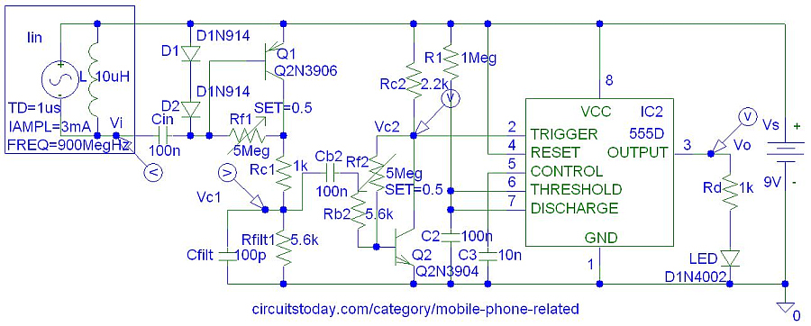
Incoming Call Indicator
This is an improvement to the circuit published at circuitlogix.com An optional component is a bypass capacitor/RC filter between two transistors to prevent amplifications of power supply fluctuations caused by second transistor drawing current from power supply. However, the second transistor (Q2) is not necessary. It is amplifies changes in Vc1.
The original circuit consisted of one NPN BC548 transistor amplifier and a 555 monostable timer. BC548 and even 2N3906 transistors cannot amplify the 900 MHz ultra high frequency (UHF) signal. Thus simulation results are not accurate. A small gain is achieved due to approximations in PSpice models. The coil picks up a lower frequency components of the 900 MHz signal that is amplified by the BC548 or 2N3906 transistors shown in the circuit above.
This circuit above was not tested and thus might not work.
|
|